25+ voltage to frequency converter block diagram
1 and its circuit diagram in Fig. On-chip negative voltage generators Low CER.
2
Sink peak current to drive the lower MOSFET of the half-bridge leg.
. So lets now settle for 256 levels sample points in each cycle of the. Like other power supplies an SMPS transfers power from a DC or AC source often mains power see AC adapter to DC loads such. The AD converter has a unique feature of being able to operate while the device is in Sleep mode.
The voltage of UC38423 rises the output decreases and the Zener tube does not conduct. The function block diagram and the ladder diagram are shown below in the figure. Circuit and working for PWM-To-Analogue Signal Converter.
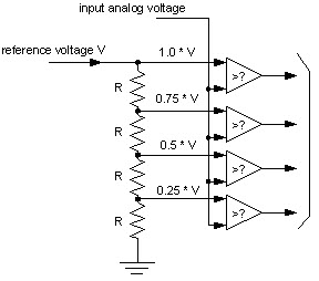
Well in order to get a ramp-up in output voltage the digital output going to the DAC should go from 0 up to 255 which corresponds to a voltage ramp from 0 to 5v. Jul 25 2022 By mohammedayman. The pin is actively pulled to.
Flyback converter with TNY279 controller IC 21 Rating Input. The voltage regulator using LM340 IC is the most used voltage regulator IC. To operate in Sleep the AD clock must be derived from the ADs internal RC oscillator.
Pin configuration MC34063AB MC34063AC MC34063EB MC34063EC. Repeatedly the output voltage will stabilize within a range depending on the voltage of the regulator. Typical system block diagram N.
Configuration Schematics and Troubleshooting. Typical system block diagram L6599 636 3 Typical system block diagram Figure 3. In this case the output spectrum is inverted.
104 Output Overvoltage. TPS54331 3-A 28-V Input Step Down DC-DC Converter With Eco-mode 1 Features 35 to 28-V input voltage range Adjustable output voltage down to 08 V Integrated 80-mΩ high-side MOSFET supports up to 3-A continuous output current High efficiency at light loads with a pulse skipping Eco-mode Fixed 570-kHz switching frequency. There are many stages of voltage gain for the op-amp used here.
The block diagram of the PWM-to-analogue converter is shown in Fig. However a 1100 kV link in China was. Main advantages of PWM DACs include simplicity low cost digitally-controlled resolution up to 10 bits or more and the possibility to obtain high output current voltage and power.
Source and 08 A min. Autonics hollow shaft. Ku band is 107 - 1275 GHz.
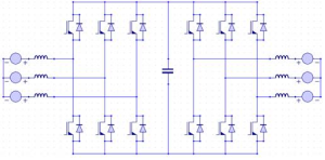
Electric Drive Block Diagram Power Source. In other words its like a step up transformer ie it step up the level of DC voltage while transformer step up down the level of AC voltage from low to high while decreases the current from high to low while the supplied power is same. Name Function 11 LVG Low-side gate-drive output.
Working and Circuit diagram of a boost converter. Our long range radio frequency remote starter and receiver works seamlessly with our latching full current magnetic starter to remotely control your converter. 15 V 1 A.
And both the converter and the motor interfaces by the power source to provide changeable voltage frequency and current to the motor. In some cases it is the other way round so that the output frequency local oscillator frequency - input frequency. The voltage of UC38423 is lowered and the output voltage is raised.
The AD9213 supports high dynamic range. You can also control your converter with our wired remotes. 22 TNY279 Functional description Figure 5 and Figure 6 shows the package and functional block diagram of TNY279 controller IC used for the design of flyback converter.
Output Voltage Limiting Protection Circuit. The average output voltage of Buck converter is controlled using two different ways ie. Frequency converter solenoid valve overhaul kits Thyristor.
This high gain helps the op. Vref drives the non-inverting input of the operational amplifier. Wireless remotes feature 500 range and include high gain omni directional antenna and a key FOB or wall mount transmitter.
A switched-mode power supply switching-mode power supply switch-mode power supply switched power supply SMPS or switcher is an electronic power supply that incorporates a switching regulator to convert electrical power efficiently. DC power source as mentioned in the previous discussion is required voltage signals. Most HVDC links use voltages between 100 kV and 800 kV.
As shown in the block diagram above the built-in reference voltage. In PWM Pulse Width Modulation the overall switch time T is kept constant while the turn ON time t on of the switch is variedIn contrast the switching period time T is varied while the turn ON time t on of the switch is kept constant in PFM Pulse Frequency Modulation. Pin ENUV BPM D and S represents.
25 GSPS radio frequency RF analog-to-digital converter ADC with a 65 GHz input bandwidth. Examples of input receive frequency band LNB local oscillator frequency and output frequency band are shown below. A high-voltage direct current HVDC electric power transmission system also called a power superhighway or an electrical superhighway uses direct current DC for electric power transmission in contrast with the more common alternating current AC systems.
VTH Threshold voltage TA 25C 1225 125 1275 V TA T LOW to T HIGH 121 129 Reg line Threshold voltage line. Lets assume its desired to get a sawtooth waveform swinging between 0-5v frequency of 10 Hz. CPU also contains other electrical parts to connect cables used by other units.
Printed evaluation board PIN 1 V OUT PIN 2 GND PIN 3 GND PIN 4 V IN. Proper analysis of the VFDs power and control circuit diagrams is essential for successful troubleshooting. C band is 34 - 48 GHz.
The power source in the above block diagram offers the necessary energy for the system. A Boost Converter takes an input voltage and boosts it. Inside Variable Frequency Drive VFD Panel.
85-265 VAC 315 A. The driver is capable of 03 A min. But before starting any analysis you must know how your system connected through VFD works.
This modulator can be used to control the op power of the supply. Voltage inverting converter Figure 18. Block Diagram Here is the block diagram for the AD converter in out PIC16F877A microcontroller.

Pin On อ เล กทรอน กส
Ac To Ac Converter Working Types And Its Supplies
How To Convert Ac To Dc Power 12v Quora
How Do The Components Of A Dc To Ac Static Converter Combine To Produce An Alternating Current Quora
Analog To Digital Converter Block Diagram Types Its Applications
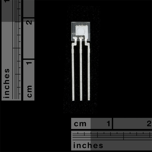
Light To Frequency Converter Tsl235r Sen 09768 Sparkfun Electronics
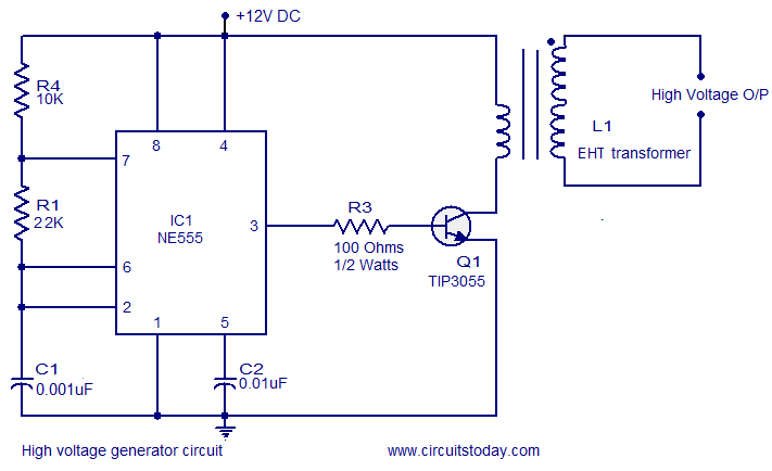
High Voltage Generator Circuit
2
How To Convert Continuous High Voltage 0 40 Kv Dc To Pulsed Dc Quora

Digispark Pro Tiny Arduino Ready Mobile Usb Dev Board Modelisme Naval Projets Arduino Arduino
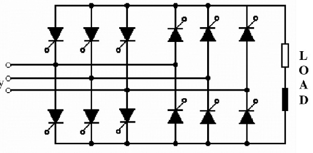
Ac To Ac Converter Working Types And Its Supplies
2
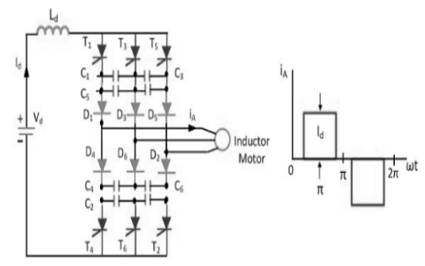
Current Source Inverter Circuit Diagram And Its Advantages
Why Do We Convert Ac To Dc To Ac In Vfd Quora
How To Convert Dc To Ac Quora
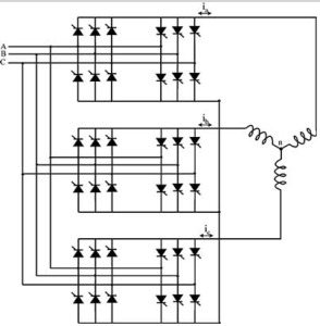
Ac To Ac Converter Working Types And Its Supplies
How Do Old 25 Year Digital Multimeters Measure Rms Voltages